Choosing a 100kw Inverter in 2026 requires more than comparing efficiency percentages. The decision affects energy yield, maintenance costs, grid stability, and business continuity. IRENA’s Renewable Capacity Statistics 2025 reported that global renewable capacity reached 4,448 GW in 2024, with solar power representing the largest share of new additions. That expansion increases demand for reliable commercial inverters, but it also creates more technical choices.
SMA’s former Chief Executive Officer, Jürgen Reinert, described the inverter as “the heart of a PV system.” The phrase is simple, but still useful. A 100kw Inverter must manage changing sunlight, high operating temperatures, voltage fluctuations, and local grid requirements. Its MPPT range, maximum input current, overload capability, cooling method, and protection rating deserve careful review. A datasheet can look impressive. Field performance may tell a different story.
The IEA’s Renewables 2024 report expects solar PV to remain the main driver of renewable capacity growth through 2030. This trend makes long-term service support increasingly important. Buyers should check warranty terms, replacement procedures, monitoring quality, and technician availability before signing a contract. A slightly cheaper unit may become expensive after one failed cooling fan or delayed spare part. That is easy to overlook. I would also question one common assumption: the highest rated efficiency does not automatically deliver the best annual return. Site temperature, shading, load patterns, and grid conditions often matter more. This guide compares those practical factors before recommending a 100kw Inverter for modern commercial projects.
A 100kW inverter should match the actual load, not only the nameplate rating. Record peak demand, average demand, motor-starting current, and daily operating hours. A factory may draw 62kW normally but exceed 110kW when compressors start together. That difference matters.
Clarify the application before comparing specifications. A solar inverter needs accurate DC voltage, current, MPPT range, shading tolerance, and grid protection. A battery inverter requires battery voltage, charge limits, discharge cycles, and communication compatibility. For backup power, define transfer time and critical loads. Seconds matter. Check whether the system operates on three-phase power and confirm the local voltage and frequency.
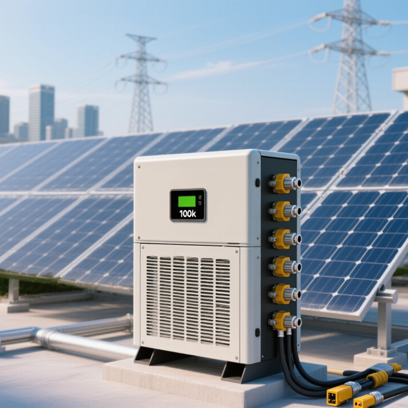
Measure the installation environment carefully. Roofs and containers can exceed 45°C, reducing available output. Dust, salt air, altitude, and poor ventilation also affect reliability. Select suitable ingress protection and leave enough clearance for service access. Review efficiency across the expected load range, not just the best published value. Harmonic distortion, surge capacity, standby consumption, and noise deserve attention too.
A practical design includes protection devices, cable sizing, grounding, monitoring, and emergency isolation. These details are often treated as accessories, which is a mistake. I have seen capacity calculations ignore future loads and replacement access. That plan looked efficient on paper. It was not. Recheck the load profile, installation drawings, warranty conditions, and maintenance skills available on site before approving the final specification.
Selecting a 100kW inverter starts with its application. A grid-tied model suits stable utility connections and direct solar export. A hybrid model adds battery charging, backup loads, and energy scheduling. Off-grid systems require stronger surge handling and reliable generator coordination. Do not compare efficiency alone. A two-level topology is usually simpler and easier to service. Three-level NPC or T-type designs can reduce switching losses and output filtering demands. They may also require more careful maintenance.
Important specifications include maximum AC current, power factor range, total harmonic distortion, overload duration, and cooling method. Liquid cooling may control heat effectively, but it adds pumps and maintenance points. Air cooling is simpler, yet dusty sites can reduce performance. Look for surge protection, insulation monitoring, anti-islanding functions, and suitable ingress protection. Confirm grid-code certification for the installation country. Communication options should support remote alarms and usable data logs. In field sizing, I have seen “100kW” systems limited by high ambient temperature or undersized cables. That detail is easy to miss. A careful comparison should include derating curves, service access, warranty terms, and replacement lead times. There is no perfect topology. The best choice depends on the site, not the brochure.
Choosing a 100kW inverter in 2026 requires more than comparing its peak efficiency. Fraunhofer ISE’s Photovoltaics Report 2024 places modern inverter peak efficiency near 98–99%. However, field output can fall with heat, partial loading, dust, and poor ventilation. Ask for European or CEC efficiency, not only the headline figure. At a busy commercial site, a few tenths of a percent can become significant energy loss.
Safety should be verified through documented testing. Check compliance with IEC 62109-1 and IEC 62109-2, plus local requirements for arc-fault detection, insulation monitoring, surge protection, and rapid shutdown. Thermal derating matters. A cabinet that reaches its limit at midday may deliver less than 100kW when demand is highest. NREL’s 2024 Annual Technology Baseline uses approximately 98% inverter efficiency for representative systems, but real projects still need temperature and load simulations.
Grid compatibility is equally important. Confirm voltage, frequency, reactive-power control, anti-islanding behavior, and fault ride-through settings under IEEE 1547-2018 or the applicable national grid code. Control options should include remote monitoring, Modbus or equivalent interfaces, power-factor control, and export limiting. The IEA’s Electricity 2024 report highlights rising solar penetration and greater flexibility needs across power systems. That trend makes controllability practical, not optional. Test integration before delivery. It is easy to underestimate commissioning time. A careful site trial can reveal unstable settings, weak communications, or nuisance trips before they affect revenue.
Selecting a 100kW inverter in 2026 starts with the site, not the catalog. Record the array’s maximum DC voltage, operating current, roof orientation, and temperature range. Cold mornings can raise voltage beyond a casual design estimate. Leave clear space around ventilation paths and service doors. Confirm lifting access, cable routes, fire separation, noise limits, and local grid requirements. An outdoor cabinet may need a higher ingress rating. That detail is easy to miss.
IEA PVPS Trends 2024 reports that global photovoltaic capacity reached about 1.4 terawatts by the end of 2023. This expanding fleet makes communication compatibility increasingly important. Check MPPT operating windows, DC oversizing limits, reactive power functions, and grid-support settings. The inverter should communicate with meters, protection equipment, and the site’s monitoring platform. Battery integration also requires matching voltage ranges and control protocols. I would not trust a perfect spreadsheet without a commissioning test.
Maintenance planning deserves equal attention. NREL’s analysis of roughly 2,000 photovoltaic systems found median module degradation near 0.5% annually. This is not an inverter failure rate, but it supports regular performance checks. Ask whether filters, fans, surge protection, firmware, and terminals can be inspected safely. Require alarm history, remote monitoring, spare-parts access, and response times in writing. A low purchase price can hide difficult service work. Inspect the actual cabinet layout before approval.
| Evaluation Dimension | Key Technical Data | Typical Requirement for a 100kW System | Installation or Selection Guidance | Verification Point Before Purchase |
|---|---|---|---|---|
| Rated AC Output | 100kW continuous three-phase output | Suitable for commercial, industrial, agricultural, and utility-scale distributed systems | Confirm that the inverter's continuous output rating is 100kW at the required ambient temperature, not only a short-term peak rating. | Review the continuous power curve, derating graph, and rated operating temperature. |
| AC Voltage and Current | At unity power factor, approximately 144A at 400V three-phase or 120A at 480V three-phase | Final current depends on the nominal grid voltage and the permitted power factor range | Select AC switchgear, cables, breakers, and transformer capacity based on calculated full-load current plus applicable design margins. | Check nominal voltage, frequency, maximum AC current, phase configuration, and local electrical-code requirements. |
| DC Input Voltage | Common commercial PV ranges are approximately 600–1,000V DC; some systems use higher-voltage designs | Must cover the array's minimum operating voltage and maximum cold-weather open-circuit voltage | Calculate string voltage at the lowest expected temperature. The maximum string voltage must remain below the inverter's absolute DC input limit. | Compare the inverter's MPPT voltage range and maximum DC voltage with the module datasheet and site temperature data. |
| PV DC-to-AC Ratio | A practical starting range is often 1.2:1 to 1.5:1, depending on climate, orientation, and curtailment limits | Approximately 120–150kWp of PV may be paired with a 100kW AC inverter when the design objective supports controlled clipping | A higher ratio can improve annual energy yield during low-irradiance periods but may increase clipping and DC equipment requirements. | Model annual yield, clipping losses, module temperature, orientation, shading, and the site's export limit. |
| MPPT Configuration | Multiple independent MPPT inputs are preferred for arrays with different orientations, roof sections, or shading conditions | Use separate MPPT channels for materially different string orientations or unequal string lengths | Avoid placing strings with different azimuths, tilt angles, or shading profiles on the same tracker unless the design software confirms acceptable performance. | Check the number of MPPTs, operating current per MPPT, short-circuit current limit, and connector arrangement. |
| Installation Location | Indoor or outdoor installation; enclosure protection commonly specified by an IP rating | Outdoor units generally require protection against rain, dust, ultraviolet exposure, and corrosive environments | Provide clearance for airflow, maintenance access, cable bending radius, lifting, and safe isolation. Avoid locations subject to standing water or direct heat sources. | Confirm IP rating, salt-mist or corrosion suitability, maximum altitude, humidity range, and required service clearances. |
| Cooling Method | Forced-air cooling is common at this power level; liquid cooling may be used in specialized designs | Forced-air systems require clean airflow and adequate space around intake and exhaust paths | Do not install vents against walls or behind obstructions. In dusty locations, plan filter inspection and cleaning intervals. | Review fan redundancy, replaceable fan modules, acoustic rating, thermal derating, and airflow direction. |
| Ambient Temperature | Many commercial inverters operate across a broad range, but full output may derate at higher temperatures | Design for the actual enclosure temperature, solar loading, altitude, and local climate rather than average outdoor temperature alone | Use shading or a ventilated equipment room where necessary. High temperatures can reduce output and accelerate component aging. | Check the full-power temperature range, derating thresholds, maximum altitude, and thermal test conditions. |
| Grid Compatibility | Three-phase grid connection with configurable voltage, frequency, power factor, and reactive-power functions | Required functions may include voltage and frequency ride-through, reactive-power control, anti-islanding, and active-power limitation | The inverter must comply with the applicable national grid code and the utility's interconnection rules. | Obtain compliance certificates and confirm settings approval with the utility or grid operator before commissioning. |
| Protection Functions | Typical functions include overvoltage, undervoltage, overfrequency, underfrequency, insulation monitoring, ground-fault detection, and anti-islanding | Protection must coordinate with upstream breakers, transformers, surge protection, and the site's grounding system | Protection settings should be reviewed by a qualified electrical engineer and coordinated with the point of common coupling. | Check protection functions, trip thresholds, response times, surge protection arrangement, and event-recording capability. |
| Battery Compatibility | A standard grid-following PV inverter is not automatically a battery inverter | Energy-storage projects require a compatible battery inverter, hybrid inverter, or AC-coupled storage architecture | Confirm battery voltage range, charge and discharge power, control communications, operating modes, and black-start requirements. | Verify compatibility with the battery management system, energy management system, site controller, and required backup loads. |
| Monitoring and Communications | Common interfaces include Ethernet, RS-485, digital inputs, and industrial communication protocols | Remote monitoring should provide power, energy, alarms, temperatures, grid measurements, and historical data | Provide a reliable communications path and cybersecurity controls. Separate monitoring availability from inverter operational availability. | Check protocol support, data points, API or gateway requirements, firmware-update method, and local data retention. |
| Maintenance Access | Serviceable components may include fans, filters, surge-protection devices, fuses, connectors, and control boards | Allow front, side, or rear access according to the installation manual | Provide safe working space, lockable isolation, lifting provisions, and a clear path for component replacement. | Confirm maintenance clearances, replacement procedures, spare-part availability, and technician training requirements. |
| Preventive Maintenance | Typical tasks include visual inspection, torque checks, thermal scanning, cleaning, firmware review, and alarm analysis | Inspection frequency should reflect dust, humidity, salt exposure, vibration, operating hours, and site criticality | Use a documented maintenance schedule. De-energize and verify isolation before opening equipment or disconnecting conductors. | Request the recommended maintenance intervals, inspection checklist, safe shutdown sequence, and service documentation. |
| Efficiency | Modern commercial inverters commonly achieve peak efficiencies above 98%, while weighted efficiency is lower | Compare weighted efficiency and partial-load performance rather than relying only on the maximum efficiency figure | Efficiency varies with DC voltage, load level, temperature, reactive-power operation, and auxiliary consumption. | Review the efficiency curve, European or weighted efficiency value where applicable, and standby consumption. |
| Noise and Siting | Fans and magnetic components generate audible noise; sound levels vary with load and cooling speed | Noise limits may matter near offices, residences, schools, or noise-sensitive industrial areas | Place equipment away from occupied rooms where practical and avoid mounting surfaces that amplify vibration. | Check sound-pressure data, measurement distance, fan operating modes, and local noise regulations. |
| System Expansion | Future expansion depends on transformer capacity, export limits, switchgear ratings, communications, and available space | Plan spare capacity in cable routes, distribution equipment, networking, and protection where expansion is expected | Do not assume that additional inverters can be added without a new protection, harmonic, or interconnection study. | Confirm parallel-operation limits, master controller requirements, and the maximum permitted plant capacity. |
| Standards and Certification | Applicable requirements may include IEC or national product-safety standards, EMC requirements, and local grid-interconnection standards | Certification requirements differ by country, voltage level, utility, and installation type | Use equipment accepted by the local authority having jurisdiction and the utility interconnection process. | Request current certificates, test reports, declarations of conformity, and grid-code test evidence. |
| Total Cost of Ownership | Includes purchase price, installation, switchgear, transformer, protection, communications, maintenance, downtime, and replacement parts | The lowest initial price may not provide the lowest lifetime cost | Compare energy yield, service response, spare-parts lead time, warranty terms, and expected downtime alongside the purchase price. | Evaluate warranty duration, response times, exclusions, availability guarantees, and long-term service costs. |
| Final Selection Rule | Choose the inverter that satisfies electrical, environmental, regulatory, operational, and service requirements simultaneously | Electrical compatibility and safe installation take priority over headline efficiency or nominal price | Complete a site-specific design review before ordering equipment, including string design, voltage drop, protection coordination, and thermal conditions. | Approve the final selection only after reviewing datasheets, installation manuals, certificates, drawings, and utility requirements. |

How to Choose a 100kW Inverter in 2026?
A 100kW inverter should be evaluated by total ownership cost, not its purchase price. Installation may require larger cables, ventilation, switchgear, monitoring equipment, and skilled commissioning. Efficiency also affects annual energy losses. A 1% difference can become significant in a high-use facility. Include expected maintenance, replacement parts, software fees, transport, and possible downtime in the calculation. A cheap quotation can become expensive after installation.
Warranty language deserves careful reading. Check the coverage period, response time, labor costs, shipping responsibilities, and exclusions for heat, dust, moisture, or unstable grids. Ask whether replacement units are repaired or supplied immediately. Keep written confirmation of service procedures. I have seen projects delayed because the warranty covered components but not field labor. That detail matters. Performance guarantees should also define testing conditions and acceptable output levels.
Certifications must match the installation country and grid requirements. Request current certificates and test reports, not only printed logos. An independent engineer should verify their scope and validity. Supplier reliability is equally practical. Review service locations, spare-part availability, technician training, delivery records, and comparable project references. A supplier with clear escalation contacts is safer than one offering the lowest price. Still, references can be selective. Check them directly, and examine recent cases. One assumption remains risky: a long operating history does not guarantee strong support in your region. A written service-level agreement can reduce that uncertainty.
This procurement benchmark assigns the highest weight to total cost and long-term reliability, followed by warranty coverage and required certifications. For a 100 kW inverter, compare the 10-year ownership cost, verify at least a 5-year standard warranty or a clearly priced extension, and request evidence of applicable standards such as IEC 62109, IEC 61000, IEEE 1547, or UL 1741 depending on the installation market.